The Complex Architecture of Fuel Distribution
Liquid petroleum fuel distribution is an intricate engineering discipline that bridges primary oil refining with end-user consumption. Behind every liter of diesel dispensed into a hospital emergency generator, construction excavator, or transport truck lies a tightly orchestrated supply chain engineered for safety, chemical stability, and precise inventory tracking.
Understanding this distribution lifecycle helps procurement managers, HSE officers, and site engineers appreciate the quality control measures required to preserve fuel specifications from refinery to combustion chamber.
The 5 Stages of the Fuel Distribution Lifecycle
1. Refining and Primary Terminal Storage
Petroleum crude oil undergoes fractional distillation, catalytic cracking, and hydrotreating at major regional refineries (such as ADNOC Refining in Ruwais). The hydrotreating phase strips sulfur compounds down to less than 10 milligrams per kilogram, producing Ultra-Low Sulfur Diesel (ULSD). The finished fuel is transferred via pipeline or coastal bunker barge to regional distribution terminals in Jebel Ali, Mussafah, or Hamriyah.
2. Quality Verification and Automated Loading Gantries
At the distribution terminal, fuel is stored in massive floating-roof storage tanks. Before commercial road tankers are loaded, laboratory technicians perform batch tests to verify key parameters: flash point, cetane index, density, copper strip corrosion, and Karl Fischer moisture content. Tankers are loaded using automated bottom-loading arms that eliminate atmospheric vapor escape.
3. Hazardous Materials Transportation Network
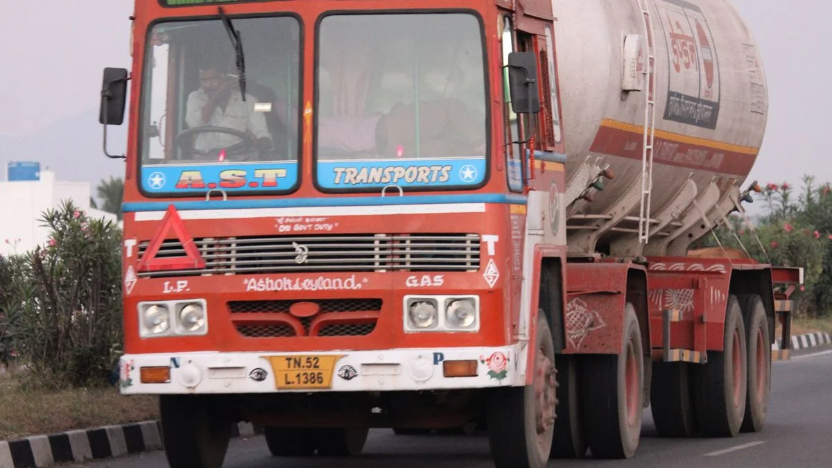
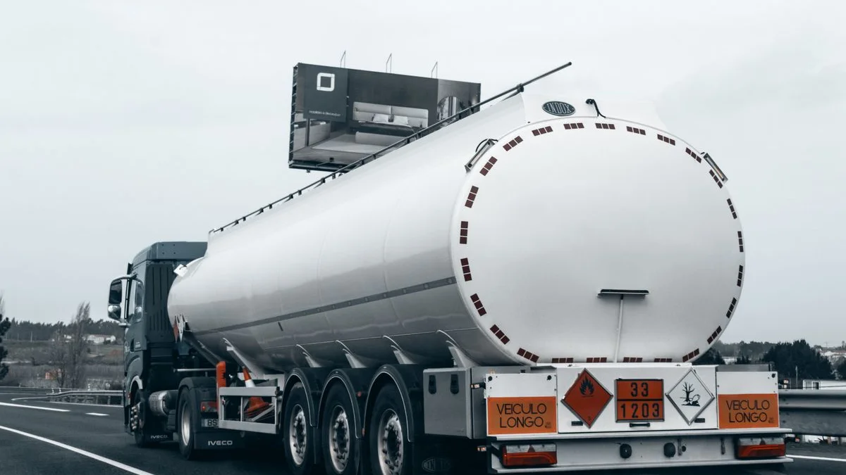
Transporting thousands of liters of combustible hydrocarbons across metropolitan areas and regional highways requires specialized road tankers engineered to international ADR hazardous material standards:
- Compartmentalized Aluminum or Steel Shells: Tanks are subdivided into multiple baffled compartments (typically 5,000 to 10,000 liters each) to dampen dangerous liquid surge during vehicle braking and cornering.
- Internal Emergency Foot Valves: Pneumatically operated shear valves mounted inside each tank compartment seal automatically if an external discharge pipe is severed in a collision.
- Vapor Recovery and Grounding Interlocks: Electronic systems verify electrical grounding to earth before discharge pumps can be energized.
4. On-Site Transfer and Cleanliness Control
During site discharge, fuel is pumped through dual-stage filtration systems designed to eliminate contaminants introduced during transport:
| Filtration Stage | Pore Micron Rating | Target Contaminant Removed |
|---|---|---|
| Primary Coarse Strainer | 50 – 100 microns | Pipe scale, rust flakes, tank weld spatter, large debris |
| Secondary Coalescing Filter | 10 microns | Free water droplets, suspended moisture, fine silts |
| Polishing Filter | 2 – 5 microns | Microscopic abrasive silica, asphaltenes, organic sludge |
5. Digital Custody Transfer and Data Logging
The final phase involves accurate volumetric custody transfer. Calibrated electronic flow meters measure dispensed volume, factor in fluid temperature to standardize billing to 15°C, and print tamper-proof delivery records that tie into enterprise inventory management software.
Learn how our UAE fuel supply and distribution network maintains absolute purity at every stage, and explore our rental generator fleet for turnkey power solutions.